

Sex Toy Motion Mechanisms for Pulsing, Tapping, Flapping and Thrusting
September 3, 2026 by
ellenyi@adultstoysgd.com
Product KnowledgePulsing, tapping, flapping, rolling, rotation and thrusting are increasingly visible in product positioning and buyer discussions. These words describe what a product is expected to do, but they do not identify the motor, transmission structure or loaded output behind the claim.
For B2B buyers, sex toy motion mechanisms should be evaluated as complete systems. The motor or actuator, reduction stage, motion-conversion components, silicone movement zone, electronics and expected resistance must be designed and tested together. A free-running sample can confirm the direction of movement, but it cannot establish the stroke, force, noise, temperature or durability of the finished product under an agreed load.
Selected Amazon US feedback illustrates the gap. In a finite sample, some tapping and flapping reviews described weak motion, tapping that was difficult to distinguish from ordinary vibration, early moving-part failure, or overly aggressive motion. These observations are not market-wide complaint rates, but they show why brands need precise motion requirements.
The engineering question is therefore not simply “Which motor is stronger?” A brushed or brushless rotary motor usually needs a motion-conversion mechanism to create tapping, flapping or thrusting. A linear electromagnetic drive can create direct reciprocating movement, but it still needs correct guidance, suspension, control and load matching. The finished system—not the motor label—determines the output.
◆ Match the Motion Claim to a Physical Output
Motion terms describe output, not motor specifications.
| Market term | Physical output to confirm | Typical drive route |
|---|---|---|
| Pulsing | Repeating change in force, pressure, amplitude or displacement | Electronic motor modulation, rotary motor plus mechanical mechanism, linear drive or air-pressure system |
| Tapping | Short repeated contact or impact | Cam/crank mechanism or direct linear reciprocation |
| Flapping | Repeated swing, opening/closing or flexible-element motion | Rotary motor plus cam/linkage, or linear drive plus lever |
| Rolling/rotation | Continuous, reversing or indexed rotary motion | Brushed or brushless rotary motor with direct drive or gearing |
| Thrusting | Axial reciprocation with a defined stroke | Rotary motor plus crank-slider/helical mechanism, or a suitable linear drive |
The same function can come from different architectures. Buyers should specify direction, stroke, frequency, duty cycle and expected load.
◆ Why Silicone Folds Are Part of the Motion System
In a flapping or thrusting product, the silicone skin is not simply placed over a completed mechanism. The moving area needs purpose-designed folds or bellows that can extend, compress and return with the internal drive.
For the flapping structures reviewed by Kenier Co, the reciprocating stroke is normally below approximately 1 cm, and the moving area may use one or two silicone folds. A thrusting structure commonly travels approximately 3–5 cm, so the number and geometry of its folds must be matched to the confirmed stroke.
Fold count alone is not a performance specification. Wall thickness, fold depth, spacing, silicone hardness, moving diameter and return behavior all affect useful travel. A structure that is too stiff can restrict motion and increase load. A structure that lacks support can distort, wander from its intended path or create difficult-to-clean gaps. Buyers should therefore approve the motor, transmission mechanism and silicone bellows as one assembly.
◆ Rotary Sex Toy Motion Mechanisms
Rotary motors are compact and widely available, but their native output is rotation. A product that promises tapping, flapping or thrusting needs a defined transmission route from the rotating shaft to the moving contact area.
◇ Brushed DC motors
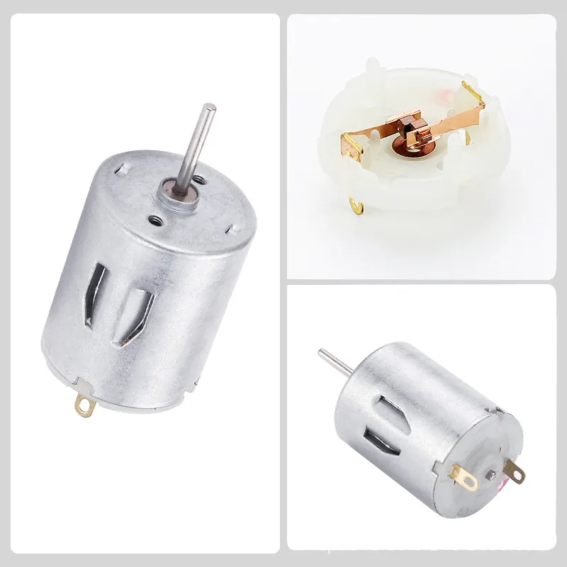
A brushed DC motor uses brushes and a commutator to switch current through rotating windings. It produces continuous shaft rotation with relatively simple control.
For rotating functions, that shaft may drive the output directly or through a reduction gearbox. For tapping, flapping or thrusting, the product needs a transmission mechanism that converts rotation into another motion.
◇ Why a gearbox is not the whole mechanism
A conventional reduction gearbox mainly changes speed and torque. Its output normally remains rotary. A complete motion drive assembly may include reduction gears, but it also needs a conversion element such as:
- an eccentric cam that pushes and releases a follower;
- a crank-slider that converts shaft rotation into linear stroke;
- a linkage that creates an opening, closing or swinging path;
- a helical motion-conversion mechanism that turns continuous rotation into reciprocating movement.
The photographed drive assembly reviewed for this article uses a molded helical transmission structure. It is a transmission mechanism, not merely an ordinary gearbox. The helical structure converts the motor’s rotary output into the required reciprocating motion.
Brushed motors are widely available and cost-effective. Limitations include brush and commutator wear, noise and overload heat. Results still depend on gearing, mechanism efficiency, battery output and alignment.
◇ Brushless DC motors
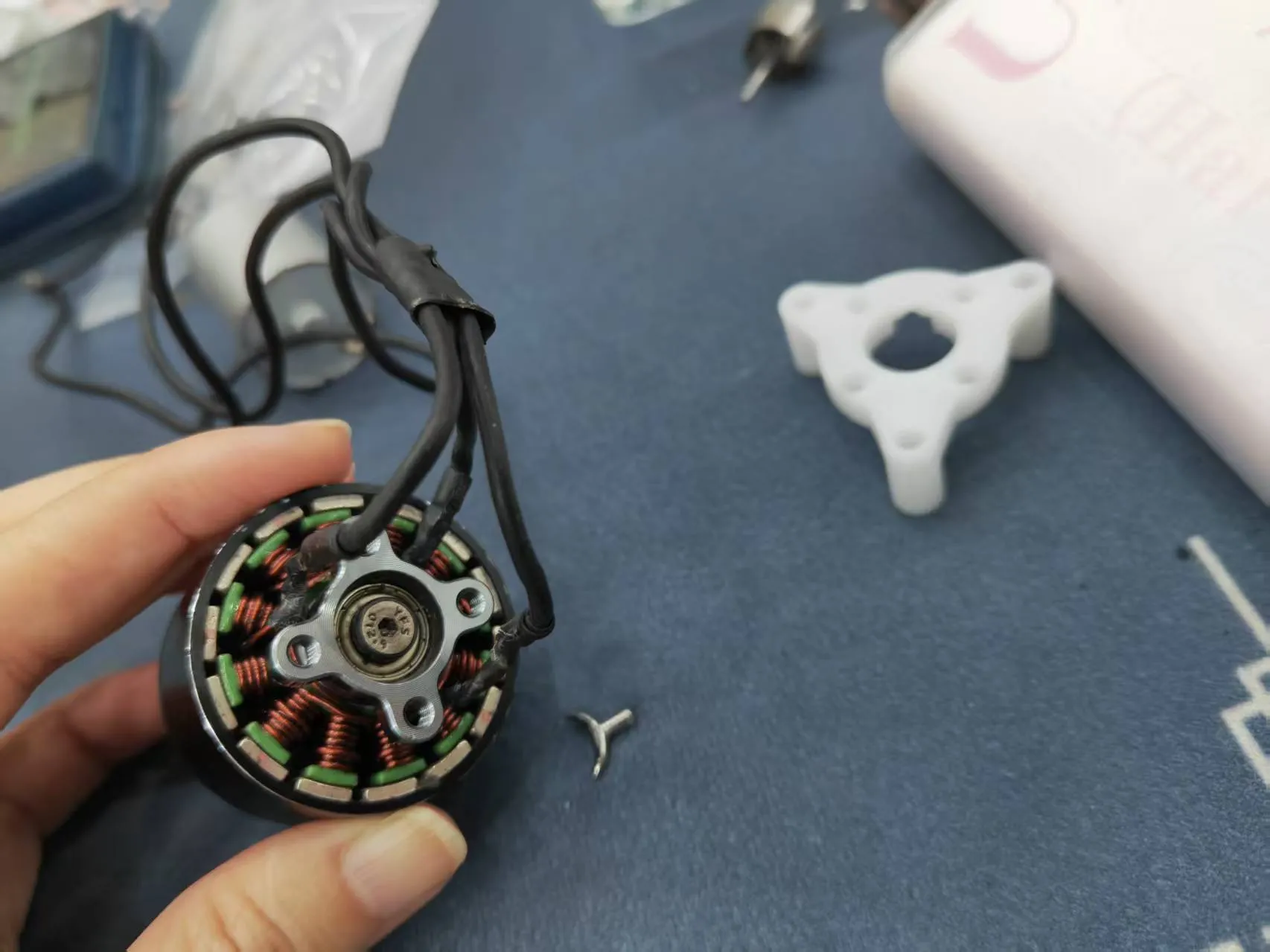
A brushless DC motor uses electronic commutation. In a common BLDC arrangement, stator windings surround a permanent-magnet rotor, and the controller switches current between phases.
With no brushes to wear, it can support longer motor life and precise control, but it requires an electronic driver. A brushless label does not prove low noise or high torque.
Most importantly, a BLDC motor still produces rotary output. It needs a cam, crank, helical mechanism, linkage or another drive module to create tapping, flapping or thrusting. For an app-controlled sex toy development project, motor control should also be reviewed with the PCB, firmware, battery, connection logic and protection strategy.
Choose it when life, control, efficiency or packaging benefits justify the added electronics and cost—not because “brushless” sounds more advanced.
◆ Direct Linear Sex Toy Motion Mechanisms
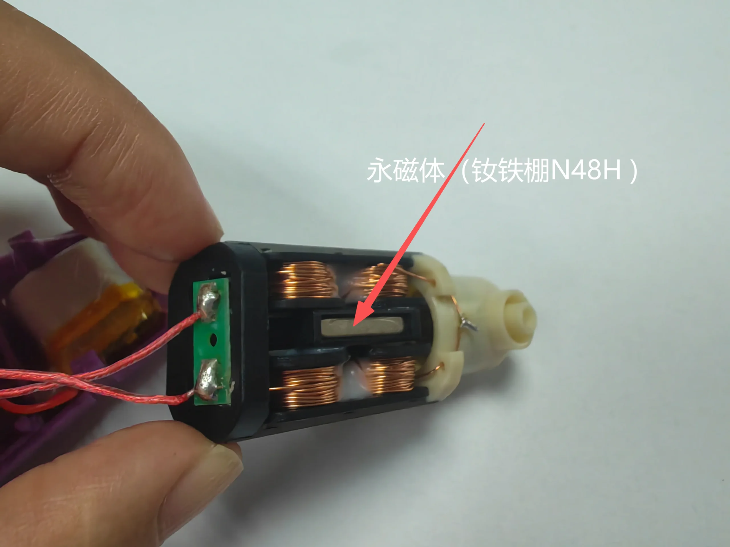
A linear electromagnetic drive creates force along a straight axis. The reviewed system combines copper coils, a permanent magnet, a laminated magnetic core or yoke and a guided moving member.
Controlled current changes the magnetic field, which interacts with the permanent magnet to produce alternating push-pull force. The laminated core guides magnetic flux and helps reduce eddy-current loss. The output is direct reciprocation rather than shaft rotation.
This removes the need for a rotary-to-linear cam or crank when the output is a short straight stroke. The assembly still needs guidance, return or suspension elements, travel limits, load connection, heat management and suitable current control.
The patented linear-drive structure reviewed for Kenier Co uses an N48H neodymium-iron-boron (NdFeB) permanent magnet together with copper coils and a laminated magnetic circuit. N48H combines high magnetic performance with higher resistance to heat-related demagnetization than a comparable standard N-grade magnet. In this design, the strong magnetic field supports direct and forceful reciprocating output for adult wellness applications.
This architecture costs more than a basic brushed motor system because the total assembly includes high-performance magnetic material, copper windings, the laminated magnetic path, drive electronics, guidance, precision assembly and thermal management. The premium is not caused by the magnet alone, and N48H does not make every linear product equally powerful. Coil design, current, air gap, stroke, moving mass, friction, control waveform and temperature still determine the finished output.
Nor does a linear drive automatically create rolling or a curved flapping path. Those outputs may still need a lever, hinge or other direction-changing structure.
◆ Why “More Powerful” Is Not a Complete Product Requirement
A product can feel weak because of an unsuitable ratio or cam profile, transmission friction, misalignment, PCB or battery current limits, incorrect bellows geometry, reduced stroke under load or heat-related control limits. The opposite problem also appears: motion may feel hard, abrupt or excessive. A larger motor or longer stroke is not automatically better. Brands need a controllable force-displacement profile matched to the product geometry.
This is why adult toy factory engineering capabilities should be evaluated at system level. Motor, structure, electronics, silicone, battery, waterproofing and assembly tolerance work as one drive system.
◆ Validate Motion Under a Defined Load
Free-running videos confirm basic motion; sample approval must go further.
◇ Measure the output that the customer will experience
Ask the supplier to define and record:
- free-running and loaded stroke;
- motion frequency at each relevant setting;
- peak and sustained force, or torque for rotary outputs;
- speed or stroke retention as resistance increases;
- stall behavior and overload protection;
- current draw, battery runtime and surface temperature;
- loaded noise in a repeatable test setup;
- mechanism wear and motion consistency after cycle testing.
“Strong,” “quiet” and “long life” are not test methods. Agree on the fixture, contact load, measurement position, mode, duration and acceptance limit before comparing samples.
◇ Test the finished enclosure
Motor-only data cannot predict the complete product. Silicone, rigid frames, seals, batteries and internal clearances change force transfer, resonance and heat. A rabbit vibrator noise-reduction case study shows why motor matching and cavity behavior must be reviewed together.
Approve the assembled sample, then define the golden-sample boundary for motion, noise, temperature and function. Production checks should use the same conditions wherever practical.
◆ Compare Rotary and Linear Drive Architectures
| Decision factor | Brushed rotary motor | Brushless rotary motor | Linear electromagnetic drive |
|---|---|---|---|
| Native output | Rotation | Rotation | Linear reciprocation |
| Motion conversion for tapping/thrusting | Usually required | Usually required | Not required for a compatible straight stroke |
| Control complexity | Lower | Higher; electronic commutation required | Requires bidirectional/current waveform control appropriate to the design |
| Wear focus | Brushes, commutator, bearings and mechanism | Bearings, electronics and mechanism | Guides, suspension/return elements, coil heat and moving assembly |
| Best fit | Cost-sensitive rotary or mechanism-driven products | Controlled, efficient or longer-life rotary systems | Direct short-stroke tapping or reciprocating outputs |
| Main procurement risk | Wear, noise, heat and mechanism loss | Driver quality, tuning, cost and mechanism loss | Stroke loss under load, heat, guidance and control matching |
There is no universal winner. A well-designed brushed motor plus helical or crank mechanism can outperform a poorly matched brushless system. A linear drive may be unsuitable for a long stroke, complex path or cost target.
Kenier Co’s broader adult wellness product development options can be used to frame the product category first. The motion architecture should follow the intended movement, product geometry, positioning, price tier and validation plan.
◆ Turn the Mechanism Into a Supplier Brief
A useful OEM/ODM brief should define the output before naming a preferred motor. Give the supplier the intended movement direction, free and loaded stroke, frequency range, contact geometry, operating modes, duty cycle, target noise conditions, runtime expectations and space available inside the product.
The development discussion should then cover:
- whether the movement will use a brushed rotary motor, brushless rotary motor or direct linear drive;
- the reduction ratio and motion-conversion structure, if rotary output must become reciprocation;
- the silicone fold or bellows geometry required around the moving zone;
- battery, PCB, current limit, control waveform and overload protection;
- material hardness, rigid support, seals, clearances and assembly tolerance;
- the test fixture, applied load, measurement point and acceptance limits;
- reports or compliance documents required for the exact model and target market;
- logo, color, instruction, packaging and channel claims that can be supported by the approved sample.
This information also clarifies the realistic customization scope. Changing a color or logo is different from changing stroke, force, bellows geometry or motion path. A mechanism change may require new tooling, structural verification, electronics tuning and additional durability testing.
◆ Control Sample-to-Production Consistency
The approved sample should become a measurable reference, not only a visual sample. Record its motion mode, stroke, frequency, force or torque, loaded noise, temperature, current draw and relevant appearance details under agreed test conditions.
During pilot and bulk production, the supplier should check the critical components and assembly points that can shift performance: motor or actuator specification, gear and molded transmission dimensions, lubrication where applicable, silicone hardness and wall geometry, moving-part alignment, PCB settings, battery output and final enclosure fit.
Packaging and product-page language should follow the validated output. Terms such as “deep thrust,” “powerful tapping” or “quiet operation” need an internal acceptance basis. They should not be created from a motor name or a free-running video alone.
◆ People Also Ask
◇ Does a linear motor need a transmission mechanism?
It does not need a rotary-to-linear conversion mechanism when the required output is compatible direct reciprocation. It still needs guidance, suspension or return elements, limits, load connection and control. A lever may also be needed for a curved or flapping path.
◇ Is a brushless motor automatically better for thrusting products?
No. A brushless motor can improve commutation life, efficiency or control, but it still produces rotary output and needs a suitable conversion mechanism for thrusting. The finished result depends on the motor, driver, reduction ratio, transmission efficiency, stroke, load and assembly quality.
◇ How can a buyer check whether motion will remain strong in use?
Specify a repeatable loaded test. Compare free and loaded stroke, frequency, force or torque, current, temperature and noise. Then repeat the check after cycle testing and against the approved golden sample.
◆ Conclusion
Pulsing, tapping, flapping, rolling and thrusting are output claims, not motor specifications. Rotary motors need a suitable sex toy transmission mechanism when the required movement is not rotary. A linear drive produces direct reciprocation but still requires guidance, control, thermal design and finished-product validation.
For brands, wholesalers and OEM/ODM buyers, the best decision is not the motor with the most impressive label. It is the complete motion system that maintains the intended output under an agreed load, stays within noise and temperature limits, survives the required cycle test, supports accurate market claims and remains consistent from approved sample to bulk production.

Latest Articles

October 14, 2026
What Can Retailers Learn About Sexual Wellness Marketing From a Brand's Customer Community?
Retailers need reasons for customers to pay attention between purchases. Repeating a discount link can leave product questions unanswered, while

October 2, 2026
How Does Sex Toy Logo Customization Work on Existing Products?
You have selected a product and prepared your brand artwork. Adding the logo looks like the easy part—until the supplier
September 29, 2026
How Is a Pornstar Dildo Developed for a Licensed Brand Collection?
A brand may have an adult performer ready to collaborate, yet still struggle to turn that agreement into a product
September 22, 2026
Adult Wellness Repeat Purchase: What Product Teams Should Review After the First Sale
A strong feature can help win a first sale. It does not guarantee the next one. For adult wellness brands,